
Wired Mowers: Troubleshooting Loop Signal
No loop signal is a very common error that can happen due to many reasons. It is important that proper troubleshooting steps are carried out to ensure the issue is identified accurately.
Finding a break in the boundary wire
A break in the loop wire is normally due to inadvertent physical damage to the wire, e.g. using a spade while gardening. In countries with ground frost, sharp stones that move in the ground can also damage the wire. Breaks can also be due to high tension in the wire during installation.
Mowing the grass too short right after the installation can damage cable insulation. Certain damage to the insulation may not cause disruptions until several weeks or months later. To avoid this, always select the maximum cutting height the first week after installation and then lower the height 1-2 steps at a time every week until the desired cutting height has been reached.
Understand the Charging Base Light
Always start by checking the LED in the charging station. This usually provides a good indication of where troubleshooting should begin. The table below indicates the meaning of the LED light in the charging station

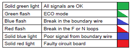
Solid green light
The LED in the charging station is solid green, but neither the front or rear loop sensor detects any loop signal:
1.Generate new loop signal. The connection between the charging station and the mower is restored. Test run the mower and continue with step 2 if the mower still cannot find the loop signal for the loop.
2.Change circuit board in charging station [ Husqvarna Dealer Only]
Green flash
ECO mode is enabled in the mower and no loop signals are at present being transmitted in the loop wires. If the mower has been removed from the charging station manually with the display cover closed, ECO mode may still be enabled (green flash) so that the loop system is not transmitting any signals. To start the loop system manually, the mower must be replaced in the charging station and the display cover opened. See also the Operator's Manual for more information about ECO mode.
Blue flash
Most likely a break in the boundary wire. Measure the resistance in the boundary wire using a multimeter. Disconnect all cables from the charging station during measuring. The resistance value for a non-faulty boundary wire should be between 0-20 Ohm.
- Value >20 Ohm: Indicates a break in the boundary wire. Locate and repair the break. The process of finding a break in the boundary wire is covered in the following sections of this document.
- Value <20 Ohm: Indicates that the boundary wire is intact. Check instead the connections to the charging station. If the fault is not remedied, change the circuit board in the charging station [Only to be performed by Husqvarna Authorized Dealer]
Solid blue light
The boundary wire is probably too long. If the boundary loop is longer than 800 meters, the strength can start to drop even if it is still sufficient.
Red flash
Probably an interruption in the F or N loop in the charging station’s antenna plate. Remove the charging station’s cover and disconnect the connector from the circuit board. Measure the resistance crosswise between the 4 pins in the cabling’s connector that has white cables connected to it.
- Value for one of the cable pairs >20 Ohm: Indicates a break in the antenna plate. Replace the antenna plate [Husqvarna Authorized Dealer only].
- Value for both cable pairs < 20 Ohm: Indicates that the antenna plate is intact. Change charging station circuit board [Husqvarna Authorized Dealer only].
Solid red light
Probably a fault in the circuit board in the charging station. Change circuit board in charging station [Husqvarna Authorized Dealer only].
Troubleshooting the Loop Signal
Follow the steps below to isolate the problem and address it.
STEP 1: Ensure that there is power to the charging base. If there is power, the light should be ON as per the table above. If there is no light on the charging base, then check the outlet and resolve as needed. If the outlet has power and the light on the charging base is still not ON, then the issue may lie within the power transformer. Reach out to support@smart-dots.com to determine the best way to replace the transformer (if under warranty then it can be replaced for no charge)
STEP 2: If the light is blinking blue, then proceed with the steps below. If it is anything other than blinking blue , please reach out to support@smart-dots.com
STEP 3: Check if the terminal connectors have a solid connection with the terminals. This can be double checked by stripping some of the wire and directly contacting it to the terminals and testing if the light on charging base is still GREEN or NOT. If it turns GREEN then replace the terminal connector and resovle the issue. If not, then continue with the next step.
STEP 4: Next step will be to try and isolate the issue using the guide wires. To do this disconnect all the wires from the back of the charging station, except for the power cable.
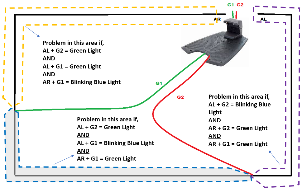
Now Connect "AL" to the "AL" port of the charging base and on the "AR" port of the charging base connect the guide wire that is closest to the AL end (In the example below G2 is closest). This will send a loop signal between the AL and G2 loop as shown in the image below.
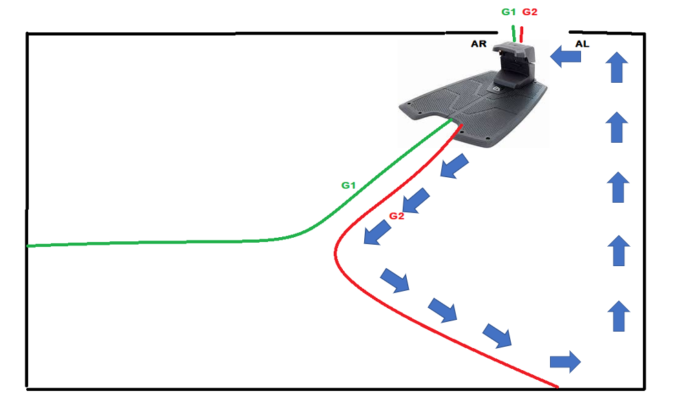
If there is no break the light on the charging base should show up as green, and this indicates that the wire in this loop is intact and the break is elsewhere.
Now continue the same thing with "AL" being connected to "AL" and then replace the "AR" port connection with Guide 1 (G1). This will send a loop signal from G1 , into the AL terminal as sown in the image below.
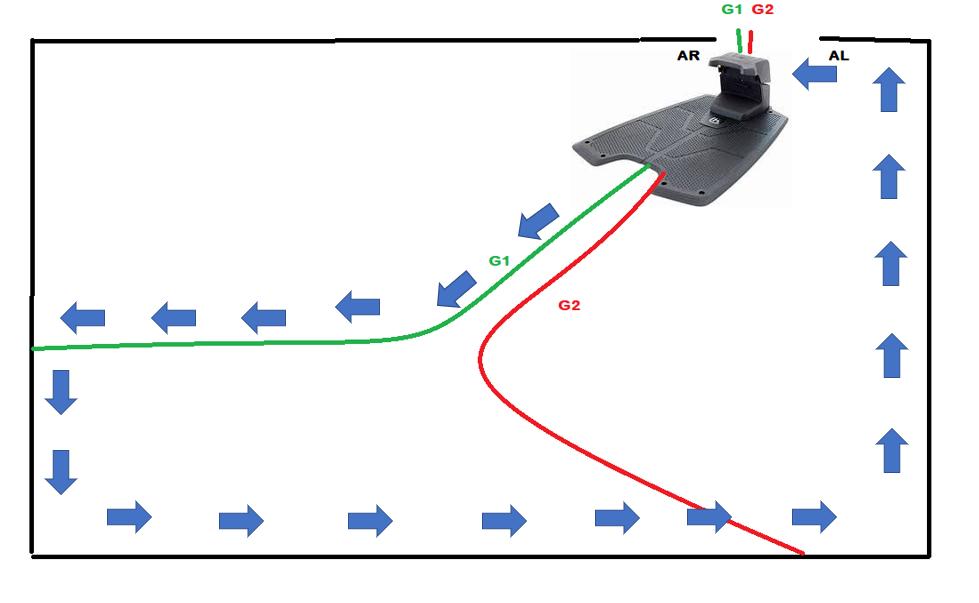
If there is no break in this loop then the light on the charging base will show up as green. This would mean that the break is most likely in the 3rd loop, which is where G1 connects to the boundary wire and the "AR" terminal.
But if the "AL-G1" combination shows a blinking blue light, then the same process should be followed, except, now the "AR" terminal should be connected with "AR" wire and the "AL" terminal should be connected with the "G1" wire. With this combination, if the light on the charging base is green then the break is between the two points where the guide wires connect. The image below helps summarize this.
Once the general area is determined, then the deep dive can be initiated using the steps below.
Note: The above narrowing down process may not work effectively if there is a break in the GUIDE wires. Also, multiple breaks may be present in many of the above 3 indicated regions causing the results to be different than what is indicated in the image above.
A wire break can be found by using a break detection tool. The tool can be purchased from SmartDots or on Amazon. The steps to identify the break are described below,
1: Disconnect all connections from the charging station including the power supply.
2: Strip some of the wire of the AR loop signal wire without damaging the connector (Preferably strip any portion of wire left after the connector)
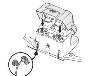
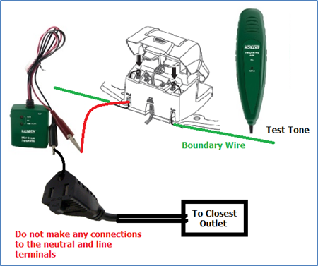
3: Connect the RED wire of the transmitter in the wire detection tool kit to the stripped AR loop signal wire. Then connect the BLACK wire of the transmitter to the closest ground (Refer to the diagram below). Alternatively, you can stick a screwdriver about 3-4 inches into the ground and connect the BLACK wire to the metal portion of the screw driver, providing a ground to the circuit.
4: Use the detector and check if you can hear a tone at location 1 (as shown in the image below). If there is a break in the loop wire, then there will be no tone at location 1 confirming that there is a break in the loop wire. If there is a tone, then the problem is elsewhere and will need to be investigated. [ The tone finder device may have to be in contact with the loop wire to ensure proper detection – This may require digging of wire at different locations before the tone tester can be used]
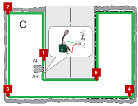
5: After confirming that there is a break in the loop signal, the next step is to efficiently narrow down the area of the break. To do so, start testing the tone at different positions starting from closest to AR wire and then moving away. In the picture shown above, that would be starting at location ‘5’ and then moving to location ‘4’, ‘3’…etc. until there is no tone heard
Ex: If a tone is heard at locations 5,4 and 3, but not at 2, then the boundary wire is broken somewhere between the points 3 and 2. Now the area can be narrowed down further by testing the tone at smaller distances moving from point 3 towards point 2. Eventually the problem area can be narrowed down to a few feet and then the wire will have to be dug out.
6: Once the broken wire is found it needs to be repaired only using the gel couplers provided in the kit. To repair first identify the broken ends of the wire and cut about an inch off with a clipper to get a clean cut using pliers. Next, two couplers will be needed to fix one break. The connections are to be made as shown in the image below.
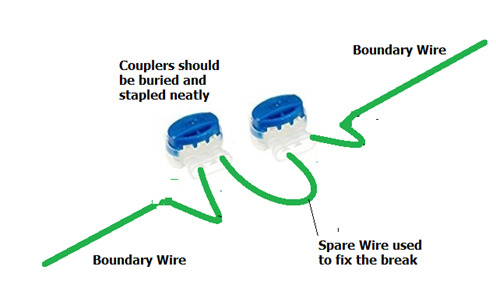
The wires can be inserted in any two holes of the couplers and the blue head should be depressed with the pliers until it clamps the wires in place – The blue head should be completely depressed for proper connection.
7: Once the connections are made, the couplers should be buried in the ground (about 2-3 inches) and the excess wire should be neatly stapled to ground level.
8: Once the fix is made, check the LED light in the charging station after powering it. If there are no more breaks, the light will be solid green. If the light is still blinking blue, then repeat from Step 1 to find other breaks in the boundary wire.
If this article was helpful then please indicate by clicking on Yes below and share your experience on Facebook. You can tag us using @smartdots22 . If you have not already liked our Facebook page, please do so by visiting to www.facebook.com/smartdots22